The headline benefits can be summarized as follows:
- Minimize transmission line loss
- Transmitter (and amplifier) linearity and efficiency
- Reduce risk of equipment and component failure and, where protection circuitry is present, ensure full power output from transmitters and amplifiers
How low is low?
HF transmitters and amplifiers are most happy when the SWR is no more than 1.5. However this is a broad generalization. The importance of low SWR tends to be proportional to power. The culprit, as we'll see, is heat. When I contested with my KX3 at 5 watts I never worried about SWR; the KX3 rarely balked at an SWR as high as 3 or even 4. I didn't bother purchasing the ATU option.
Most 100 watt transmitters will not roll back the power until the SWR is 2.With the FTdx5000 at 200 watts it appears to reduce output when the SWR exceeds 1.5. This seems to be a sensible choice. Rare is the broadband kilowatt amplifier that will not turn down the power when the SWR is 1.5, and may go so far as to shut down until the problem is resolved. You don't want that happening in a contest.
Even if your equipment will comfortably handle higher SWR, with or without a tuner, there are still benefits to be had. High SWR affects more than just the transmitter.
SWR and impedance
I have always found that talking about reflections, reflected power and return loss not terribly effective when it comes to gaining a basic understanding of RF networks. For me it is far easier to approach the problem as about impedance: Z = R + jX.
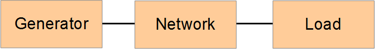
Now we assume a generator that is optimized to transfer power to a load of 50 Ω, with an optional network in between. The network can be as simple as a transmission line with a characteristic impedance of 50 Ω. If we further assume the transmission line is lossless it essentially disappears. In fact for the purpose of this discussion I'll assume that we have a transmission line of this type. At HF with large diameter hard line, such as the Andrew Heliax I use, this is pretty close to reality.
For a load impedance that is not 50 + j0 Ω there is a mismatch. That is, power is reflected back toward the generator where, in our steady state case, appears as a complex impedance as determined by the transmission line length. This is easiest to see with a Smith chart.
 |
| Smith Chart with circles drawn for SWR 1.5, 2 and 3 (original figure from Wikipedia, by Wdwd) |
Once you know the load impedance (and therefore SWR) you walk around the Smith chart to find the impedance at the generator end of the transmission line, with each completed circle representing ½λ of electrical length. Thus you can estimate the impedance seen by the transmitter.
Why broadband transmitters demand low SWR
An RF active circuit is a finicky creature. Departures from the designed load impedance (output port) change the behaviour of the circuit. Its efficiency will decline and it may have reduced linearity resulting in additional distortion products. Misbehaviour can increase for maximum excursions of R and X for a constant SWR. In years past it was not unusual for hams to change the transmission line length (values of R and X) to tame transmitter difficulties when faced with a high SWR.
If the load is 50 Ω all is well. The generator (our transmitter or amplifier) is happy, transmission line loss is as low as it can be and the load (antenna) accepts all the power. In real life it is never that simple.
Consider transmitter efficiency. Assume that our 1,000 watt transmitter operating in AB class has an efficiency of 60%, therefore generating 670 watts of heat. This heat which is produced in the active devices (tubes or transistors) and other elements of the circuit must be removed to prevent component destruction. This should come as no revelation to anyone who is not new to the hobby.
The challenge grows as the impedance at the output port moves from the optimum value. This is primarily seen as a reduction in its efficiency, meaning more heat produced for a constant output power, which is how most of our equipment is designed to perform. For example, if efficiency drops to 50% the heat produced rises to 1,000 watts, or 330 watts more than in the optimum case. In addition, high SWR (large R and X variation) can place high current or voltage at critical locations that can lead to component failure.
You can see how fragile our high power equipment can become when faced with a mismatch. Equipment size and cost (active devices, transformers, coils, etc.) can be increased to handle more heat, current and voltage, or we can lower the SWR threshold at which power is rolled back. Although efficiency depends on the specific values or R and X it is easier and more reliable to measure and trigger on SWR.
With that overview I have covered enough about mismatch behaviour to continue onward without exhausting my limited knowledge of the subject. I will leave the gory details to the engineering literature where you can indulge yourself if you want to learn more.
Agility
Any contester will know that operating agility is a competitive edge. When all antennas have low, flat SWR you can achieve the following:
- Switch among antennas on a band without the need to adjust amplifiers or tuners
- With a broadband amplifier, switch bands without the need to adjust amplifiers or tuners
- No time wasted during band and antenna changes, and therefore more potential QSOs
- Quickly move multipliers to another band without losing your run frequency or losing the multiplier due to your delay in setting up on the other band
- Avoid mistakes that weaken your signal during band and antenna changes, either due to inadvertent high SWR, tuning error or amplifier dropping offline
- Broadband amplifiers with automatic band switching, or at least automated tuners that react to frequency changes
- OWA yagis, even at the expense of serious mechanical challenges on 40 meters
- 4-squares on 80 and 160 meters, which excel at broadband SWR and performance in comparison to alternatives
The rest of us can pick our spots to improve our agility since we cannot do it all. There exist inexpensive shortcuts such as sticking labels on manually tuned amplifiers to mark the settings for each band, band segment and antenna. For my own station plan I have a lot to think about.
There are a variety of other benefits to contesters of low SWR antennas. I believe the time spent delving into SWR will show its value in the following sections.
Transmission line loss
I'll keep this brief since every ham ought to know that a mismatch increases transmission line loss. For contesters with long runs to reach antennas on high towers the impact can be worse. When the SWR is kept low the design loss objective can be met with less expensive transmission line.
Use software such as TLW (comes with the ARRL Antenna Book) and online calculators to quantify the loss of transmission line alternatives and the impact of SWR. On the higher HF bands and at VHF and UHF the results can be enlightening.
Power division for stacking
Equal power division for effective stacking can only be accomplished when the impedances of the antennas is equal. A power divider, whether done transformer or phasing lines, is essentially just loads connected in parallel, and we know from Ohm's Law that the power in each load element depends on the impedance of each.
The most common solution is to use identical antennas in the stack. It is certainly possible to use dissimilar yagis if the impedances are near equal, in both R and X components. This is typically only practical when the SWR is low for all the antennas. An alternative is to insert a network at the feed point of at least one antenna that is carefully designed to match the impedance curves of the other(s).
Failure to closely match antenna impedances will send most of the power to one antenna, undercutting the objective of stacking and may present a high SWR to the transmitter. When a transformer is used as a power divider the mismatch due to a poor SWR on one or more antennas in the stack can alter the transformation ratio and increase heating in the ferrite core on which the transformer is wound. When running high power that heat can permanently damage the ferrite core.
Filters and stubs
The band pass filters used by many contesters protect receivers and reception quality by removing harmonics and other out-of-band emissions from a second transmitter, whether SO2R or multi-op. Most often they are placed between transceiver and amplifier. Sometimes (and more expensively) they are placed between the amplifier and antenna. In the former case stubs may be used to notch harmonics since they are a low cost alternative to high power band pass filters. Triplexers for sharing tri-band yagis utilize both band pass and band stop filters.
A filter is a network element like any other; look at the picture up above and imagine that the filter is the network between generator and load. Some manufacturers provide excellent technical resources on how their filters work and should be used. Here's a quick quiz: where does the out of band energy go?
Even if you don't know the answer there are just a few possibilities: dissipated as heat; grounded; or reflected. In the latter case this would be a high SWR outside the pass band, while in the former cases the impedance would have to be near 50 + j0 Ω, which is that of a pure resistance. It should be self evident that within the pass band the impedance would also be near 50 + j0 Ω. As you can see, impedance is a useful way to think about filters. Provided that harmonic energy is a small percentage of the total transmitter power (as it should be!) how that energy is handled by the filter will not noticably affect the transmitter.
Be aware that the source and load are integral components of the filter design. The filter only does what you expect if these are close is those impedances are close to 50 + j0 as well. Depending on the filter design a high SWR at the antenna port can degrade filter performance both within and outside the pass band. If you want your filter to work at its best antennas with low SWR are desirable. A few decibels can be enough to cause grief on other bands.
Performance of transmission line stubs to reject (reflect) the harmonic energy they are tuned for is sensitive to placement on the transmission line. Although the SWR may be low at the fundamental that is typically not the case for the harmonics. For best performance a predictable impedance is required and that will depend on the generator, load and stub placement. Since K9YC covers this topic so well I'll point you there for the details.
Common mode chokes
Preventing antenna currents on the outer surface of transmission lines protects the pattern of directive arrays, ensure power goes where it is most effective and reduce noise on reception. Common mode chokes at all antenna feed points are needed. Chokes typically take the form of 1:1 current baluns or coiling the coax on a ferrite or air form.
In the case of a 1:1 balun there is less core heating when the SWR is low; as with stacking power dividers (see above) efficiency suffers for high SWR and reactive loads. Coax coils wound on ferrite toroids are less susceptible to high SWR. Air core coax coils are sensitive to frequency and therefore less effective, which is a shame since they can handle higher power even when the SWR is high.
Relays
The typical contest station has dozens of relays to manage antenna switching and sharing among operator positions. If an antenna has a high SWR the current or voltage at the electrical distance of a relay from the antenna dictates whether the relay contact see abnormally high voltage or current. These can affect relay reliability and lifetime by arcing or heating when using high power.
Although relays with wider contact spacing and current capacity can reduce the impact they are often not used in commercial antenna switches. You can build your own switches if you insist on operating with high SWR antennas. Keep in mind these relays are larger, a little more expensive, and the coils require 100 ma or more at 12 VDC versus ~40 ma for the ones typically found in these products.
Conclusions and suggestions
Non-contesters can get by using antennas with high SWR over parts of the band, for the most part not suffering from many of the problems discussed. Contesters should reconsider if they have not dealt with these issues. It is something that I am striving for in my antenna farm, although at this time I have progressed very far.
All my yagis are either tri-banders or have loaded elements, which results in high Q behaviour and therefore higher than desirable SWR over significant parts of every band. My wire antennas for 80 and 160 meters fare a little better. Since these antennas are temporary, power is limited to 200 watts and I don't yet do SO2R or multi-op I am able to get by without too much trouble. For the antenna with the highest SWR on a band I train the rig's ATU for it and then have to remember to switch the ATU in and out depending on the antenna in use. Of course I sometimes forget.
I propose the following suggestions for the contester with a growing antenna farm to achieve the lowest possible SWR:
- Avoid multi-band yagis, and especially those with traps. Multi-band yagis with interlaced elements or, better yet, mono-band yagis should be used.
- Consider OWA yagis despite the complication of an additional element for a given boom length. Low SWR across the band can be readily achieved from 40 meters on up.
- An alternative to OWA yagis when boom lengths are long are the optimized yagis documented in the ARRL Antenna Book and elsewhere. These yagis can achieve low SWR across the band from 20 meters on up.
- If a 40 meter yagi is to have only 2 elements a Moxon is a good choice. Convert an XM240 or build a W6NL Moxon from scratch.
- On 80 meters you best choice for low SWR from 3.5 to 3.8 MHz is a 4-square. Many contesters use 4-squares on 40 meters with good results, and is a far less challenging project than a large yagi.
- Use good quality coax and test it periodically. Old coax, even Andrew Heliax, will wander away from 50 Ω as time passes. From the testing I've done a lot of this old coax tends to develop a lower characteristic impedance, reaching as far as 45 Ω. That's an SWR of 1.1 to a perfect dummy load.
- Matching networks, where required, should be placed at the antenna feed point, not in the shack. If necessary make the network switchable to change the low SWR range between band segments depending on the contest mode (CW, SSB, RTTY).
No comments:
Post a Comment
All comments are moderated, and should appear within one day of submission.